Upgrading and consolidating Commodore 128 ROMs
5 minute read Published: 2014-04-09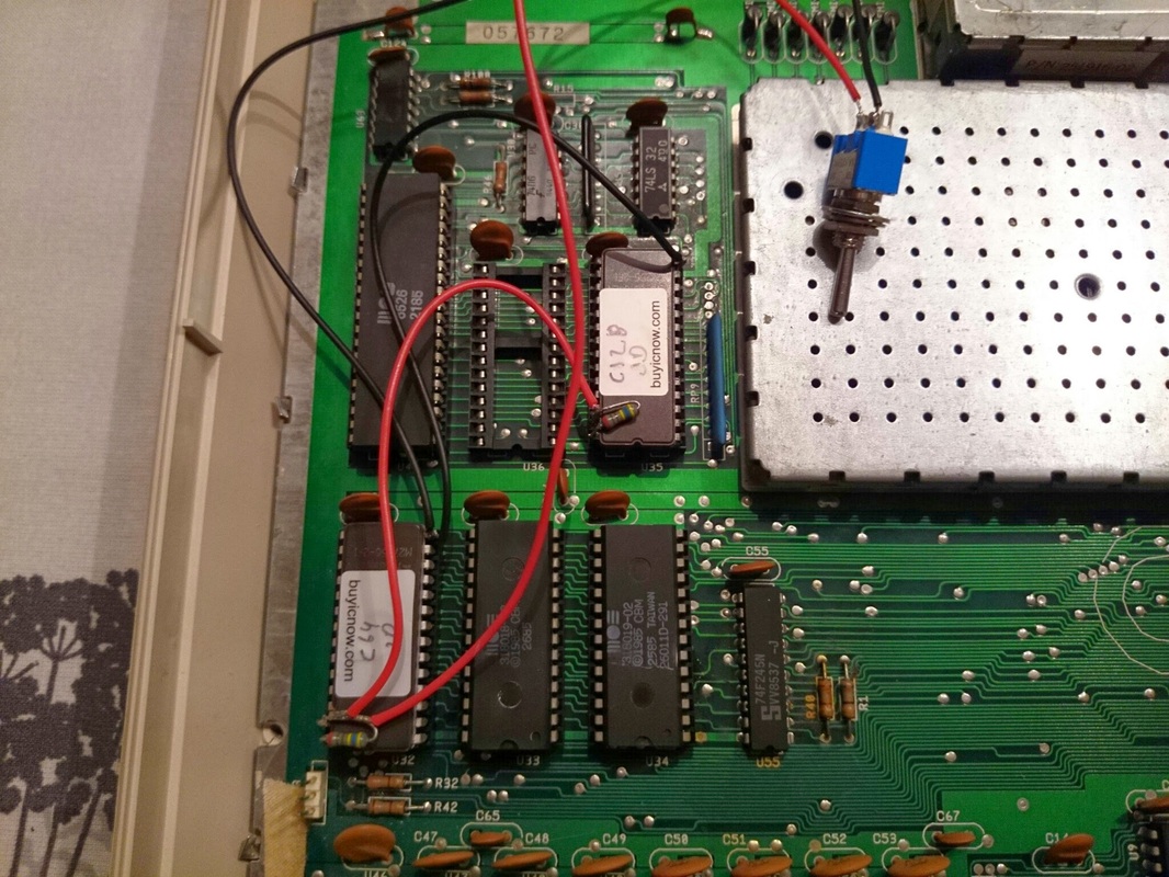
Yeah, I'm not really sure why I used two pull-up resistors - the switch controls an address line on both ICs at the same time, so that's kind of wasteful. Anyway, it worked fine.
This Commodore 128 is an older model, the kernal and BASIC ROMs are the first revisions and not the later, bug-fixed versions. But you don't install the old versions when you replace the ICs, do you? That would make no sense. By upgrading the kernals I now had a Franken128 with new kernals and old BASICs. That's easy to fix, just replace the two BASIC ROMs with two new EPROMs, right? Right.
A better way
But it turns out there's a better way. The Commodore 128DCR (128D, cost reduced) only uses two ROMs, not four. The old 128 also supports this mode via jumpers - almost. There's a slight hardware bug, but that's easy to work around.
Two EPROMs instead of four? Sounds like something I want to explore.
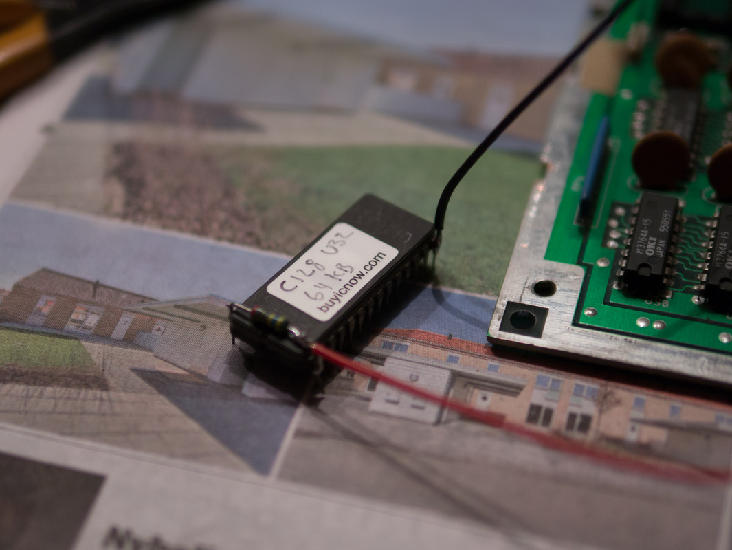
In this mode the new U32 ROM is a 32 KiB part and consists of the old U32 (C64 kernal & BASIC, 16 KiB) followed by the old U35 (C128 kernal, 16 KiB). I want to be able to switch in JiffyDOS, so I'll need a 64 KiB part and pull A15 high when I want JiffyDOS. I need the following layout:
$0000 - C64 kernal & BASIC
$4000 - C128 kernal
$8000 - C64 JiffyDOS kernal & BASIC
$C000 - C128 JiffyDOS kernal
This layout is easily produced by concatenating these ROM images:
$0000 - basic.901226-01.bin (C64 BASIC)
$2000 - kernal.901227-03.bin (C64 kernal)
$4000 - kernal.318020-05.bin (C128 kernal)
$8000 - basic.901226-01.bin (C64 BASIC)
$A000 - JiffyDOS_C64_6.01.bin (C64 JiffyDOS kernal)
$C000 - JiffyDOS_C128_6.01.bin (C128 JiffyDOS kernal)
Using MS-DOS, it's as simple as
C:\>copy /b basic.901226-01.bin+kernal.901227-03.bin+kernal.318020-05.bin+basic.901226-01.bin+JiffyDOS_C64_6.01.bin+JiffyDOS_C128_6.01.bin U32_64KiB.bin
The new combined BASIC ROM will be a 32 KiB part, reside at U34 and consist of the old U33 (low BASIC ROM, 16 KiB) followed by the old U34 (high BASIC ROM, 16 KiB)
This is simply the basic.318022-02.bin ROM image as found in the 128DCR.
Preparing the C128
All in all, there are three jumpers that let us put the 128 into the two ROMs mode.
- J3 - instructs the 8721 PLA to use 32 KiB ROMs, the signals generated on the ROM1-ROM4 lines sent to the ICs at U32, U33, U34 and U35 as "output enable" will be different.
- J4 - supplies address bus A14 to A14 at U34
- J6 - supplies 64/128 mode line to A14 at U32
Can you spot the bug? Well, here's what happens. The problem is the BASIC ROM, U34. The CPU needs to see U34 at $4000-$BFFF. If we simply mirror A14 on U34's A14, A14 is high when addressing the low 16 KiB ($4000-$7FFF) and low when addressing the high 16 KiB ($8000-$BFFF). This is the opposite of what we want. One solution is to swap the two 16 KiB banks before burning the EPROM. Another solution, which the 128DCR uses, it to supply A15 to U34's A14 instead, as A15 is low when accessing $4000 and high when accessing $8000. Problem solved. Both solutions work, but only the latter makes the setup compatible with ROMs from the 128DCR and that's probably a good thing to do.
Let's get to work! J3 is easily located and closed:
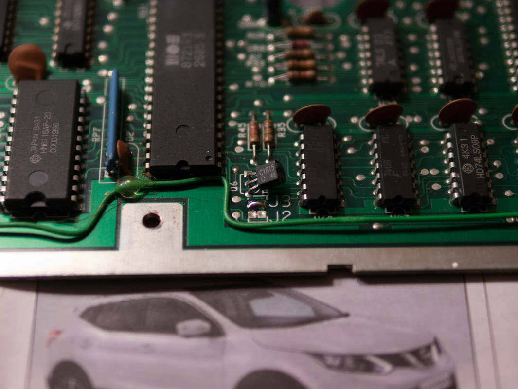
J6 is pretty easy too:
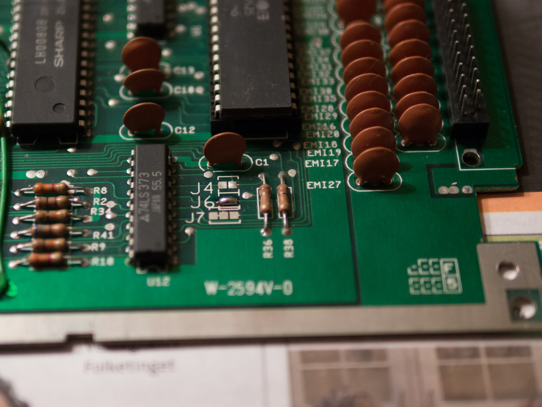
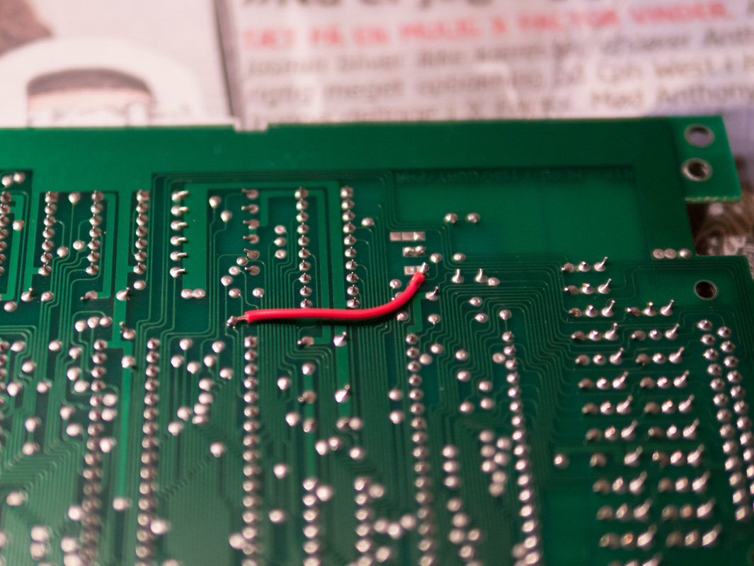
But for our troublesome friend, J4, I chose to keep things neat and installed a wire on the solder side of the board. A15 can be found in many places (probe around using a multimeter or trace lines from the CPU), here I got it from a nearby via. The J4 pad closest to the edge of the board is the one that goes to U34.
The C128 is now ready for the bigger ROMs.
To be able to switch in JiffyDOS, all that remains is to solder a 4.7k pull-up resistor between pin 28 (VCC) and pin 1 (A15) on the U32 ROM, and a switch between pin 1 and pin 14 (GND). A15 is then pulled high, and JiffyDOS switched in, until the switch is closed and A15 goes low. When seating the chip in the socket, pin 1 should be bent out slightly (or cut off) so it doesn't make contact with the socket, as the board supplies 5V to it.
That's it, install the two ICs and the Commodore 128 now uses a little less power and produces less heat.